
LEVEL: MEDIUM

We got a request from the school to provide a few traffic signs. The kids will start to learn about traffic: rules, how to behave, etc. We had 3 days and on the first day, checking up on the stocks of materials, we decided we will make a proper traffic light, with button for pedestrians and all.
This is also our first project using ATtiny microprocessor. You can program it using your Arduino Uno and Arduino IDE so it really wasn't very difficult.
LIST OF MATERIALS:
- ATtiny85
- 8 pin DIP socket (optional)
- STP16C596 - LED driver
- Push button switch
- On/Off switch (1P1T)
- 6 red LEDs
- 3 yellow LEDs
- 6 green LEDs
- 0.33uF capacitor
- 0.1uF capacitor
- 220 Ohm resistor
- perfboard
- 5 plastic eggs (from children toys like Cars, Planes, Hello Kitty...)
- aluminium foil
- baking paper (or some other semitransparent foil)
- black self-adhesive contact paper
- cardboard box and tube (PVC tube could also work)
- bunch of wires, female and male pins
- hot glue
BOX

You will need appropriate size cardboard box. Luckily, we had one from the iron we bought recently. We also have a bunch of small plastic eggs. We used the pointier half as a reflector. Depending on the size and shape, you might test and use the other half.
Using the eggs as template, mark holes on the cardboard box. Make sure that when you put the egg halves inside, they won't collide.
Also, mark a hole on the top for the ON/OFF switch and also on the bottom for the support tube. We found that the simplest way to fix the box is to cut a hole for the tube right next to back side. Putting tube inside for about 5 cm and use 2 zip-ties to tie it to the back of the box (we also added two small metal pieces to reinforce the cardboard, you can check it in the gallery)
Cut the holes with a sharp knife or a cutter. Then wrap the entire box with black contact paper. If you apply it carefully, you can get a very nice and smooth finish. Then cut the contact paper over the holes. Check again with the egg halves to see how well they fit. The best is if they have gentle contact with the edge. Hot glue will do the rest.
Next thing you will need is cut the circles of baking paper, about 0.5-1cm larger than the holes for the lights.
Then you cut the rings from contact paper: inner diameter is the diameter of the hole, and outer is a bit larger than the diameter of the baking paper. For the pedestrian side, it's nicer if you can cut out the contact paper with signs that are customary in your region.
LED LIGHTS

However, after testing the reflector configuration, we realised that the light was too weak (especially behind the semitransparent baking paper). Then we decided to up it to 3 LEDs per light and it looked OK. Also, we had to add a LED driver IC.
Note: STP16C596 is a 16 channel LED sink that can take up to 120mA per channel. So, assuming a standard 20mA per LED, we could actually put 6 LEDs per channel, and since only 5 channels are needed, we could dedicate 3 channels per each light, a whooping 18 LEDs. But, for that we would probably need bigger reflectors, and also a bigger battery pack. However, if you need more light...the option is there.
Cut a square piece of perfboard big(small) enough to hold 3 LEDs. Bend, cut and solder together LED pins (cathodes with cathodes, anodes with anodes). Use shrink tube if necessary to avoid short-circuit. Make sure you mark which contact is which. Then you solder a thin wire to each group. Make sure you leave enough wire to make contacts outside of the box. About extra 10-15 cm sticking out of the box should be enough. On the free ends of the wires crimp/solder female pin contacts.
Cut a small hole (about 1cm in diameter) at the bottom of the egg half. then line the inside with aluminium foil. We used a bit of hot glue to make it stick. Pass the wire trough the hole and pull the LED setup inside. See that it fits nicely. Then pull out the LED setup and put a blob of hot glue at each corner. Pull it back gently inside the reflector and let the glue cool down and sticks it into place.
BOX ASSEMBLY
Apply a ring of hot glue on the border of the reflectors. Depending how sizes of your holes and reflectors line up, you might decide to place eggs from inside or outside...it's really up to you. Take care not to mix order of lights.
When all lights are in, place baking paper circles over the holes (you can gently glue in pew pints, just to make them stick. Then place black contact paper rings over them and secure them in place.
PEDESTRIAN BUTTON

Luckily, we had a ~6 cm diameter cardboard tube. You can also use 2-3" PVC pipe.
Size up the tube to the height of the kid. Also, determine which height is appropriate for the push button (~1m).
Drill a hole in the tube big enough to pass 2 wires. We made a button support from cardboard. Exact dimensions depend on the tube diameter you have and size of the push button.
Fix the push button in the hole and pass the wires all the way to the top of the tube. Again, leave enough wire to pass the top of the box by 10-15cm. Crimp/solder female pin connectors to the free ends.
ELECTRONIC CIRCUIT

Take a piece of perfboard and solder to it a following circuit. In addition, we put a ON/OFF rocker switch between the battery pack and the circuit. That is optional, you can always just open the top of the traffic light box and have battery pins there to connect/disconnect.
220 Ohm resistor is adequate for our LEDs. Chose your resistor appropriately. If you are not sure, for most of the vulgaris domesticus LEDs, something of the order of 200-300 Ohm is adequate.
Note: I'd really advise you to solder on the perfboard an 8 pin DIP socket for the ATtiny85. This way you can take it out and reprogram it if you want to change something (timing modes, or whatever you feel like)
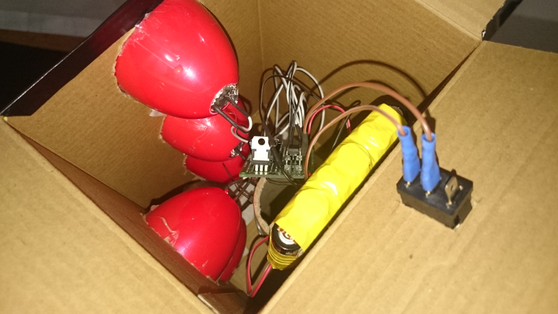
Now you just have to put it together (how exactly, it really depends on what you have on your hands, you can use the photo gallery for ideas). Connect the battery and the electronic circuit to the LEDs, fix it all inside the box and voila
CODE
Don't forget to program your ATtiny with the following code. If you have any question regarding the code, you can ask in the comments, send an e-mail...the usual.
// semafor_attiny85.ino
// author: KnitsandBits.net
//
#define PIN_HIGH(pin) digitalWrite(pin, HIGH);
#define PIN_LOW(pin) digitalWrite(pin, LOW);

const int SDI = 2;              //LED driver connections
const int CLK = 1;              //LED driver connections
const int LE = 0;   //LED driver connections
const int startButtonPin = 3;   //pin that will determine if start button is pressed

unsigned int LED_matrix = 0x0000;   //variables for LED fnctions
unsigned int mask = 0x0000;

void setup() {
    pinMode(startButtonPin, INPUT_PULLUP);    //default state is HIGH, goes to LOW when  Start button is pressed
    pinMode(SDI, OUTPUT);           //LED driver configuration
    pinMode(CLK, OUTPUT);
    pinMode(LE, OUTPUT);
    BLINK(3, 70);
    LED_ON(3, true); // start setup
    LED_ON(4, false);
}

void loop() {
    int startButtonPressed = digitalRead(startButtonPin);
    if(startButtonPressed == 0){
        //wait a few seconds
        delay(1000);
        //blink green 3 times
        BLINK_PIN(3, 3, 400);
        //turn off green, turn on yellow
        LED_ON(3, false);
        delay(400);
        LED_OFF(3);
        LED_ON(2, false);
        delay(1000);
        //turn off yellow, turn on red
        LED_OFF(2);
        LED_ON(1, false);
        //turn off pedestrian red, turn on pedestrian green
        delay(1000);
        LED_OFF(4);
        LED_ON(5, false);
        //wait pedestrian time
        delay(5000);
        //blink pedestrian green 5-6 times
        BLINK_PIN(5, 6, 300);
        //pedestrian green is off at the end of blink_pin
        LED_ON(5, false);
        delay(300);
        LED_OFF(5);
        //turn on pedestrian red
        LED_ON(4, false);
        //turn on car green
        delay(1000);
        LED_OFF(1);
        LED_ON(3, false);
        //wait minimum car time
        delay(8000);
    }
    delay(20);
}

//*************   LED control functions   *************
void LED_ON(int n, boolean clr_mem){  // LED:  n=1...16, n=0 turn off all, n=17 turn on all
    if (clr_mem==true) {                // resets (turns off) all LED
        LED_matrix=0x0000;
    }
    if (n==0) {
        LED_matrix=0x0000;
    }
    else if (n==17) {
        LED_matrix=0xffff;
    }
    else {
        mask = 0x0001<<(n-1);
        if ((mask & LED_matrix)==0x0000) {
            LED_matrix = mask | LED_matrix;
        }
    }
    PIN_LOW(CLK);
    PIN_HIGH(LE);
    for (unsigned int cnt=0; cnt<16; cnt++) {
        if ((LED_matrix >> (15-cnt)) & 0x0001){
            PIN_HIGH(SDI);
        }
        else {
            PIN_LOW(SDI);
        }
        delay(1);
        PIN_HIGH(CLK);
        delay(1);
        PIN_LOW(CLK);
    }
    PIN_LOW(LE);
    PIN_HIGH(LE);
}

void LED_OFF(int n){ // LED:  n=1...16
    if (n>0 && n<17){
        mask = 0x0001<<(n-1);
        if ((mask & LED_matrix)!=0x0000) {
            LED_matrix = ~mask & LED_matrix;
        }
        PIN_LOW(CLK);
        PIN_HIGH(LE);
        for (unsigned int cnt=0; cnt<16; cnt++) {
            if ((LED_matrix >> (15-cnt)) & 0x0001){
                PIN_HIGH(SDI);
            }
            else {
                PIN_LOW(SDI);
            }
            delay(1);
            PIN_HIGH(CLK);
            delay(1);
            PIN_LOW(CLK);
        }
        PIN_LOW(LE);
        PIN_HIGH(LE);
    }
}

void BLINK(int n, int t){   //"n" is number of blinks, "t" is time in miliseconds between blinks
    for (int k = 0; k < n; k++){
        LED_ON(17, true);
        delay(t);
        LED_ON(0, true);
        delay(t);
    }
}
void BLINK_PIN(int p, int n, int t){ // p=pin, n=number of blinks, t=time of each blink
    for (int k = 0; k < n; k++){
        LED_ON(p, false);
        delay(t);
        LED_OFF(p);
        delay(t);
    }
}


No comments:
Post a Comment